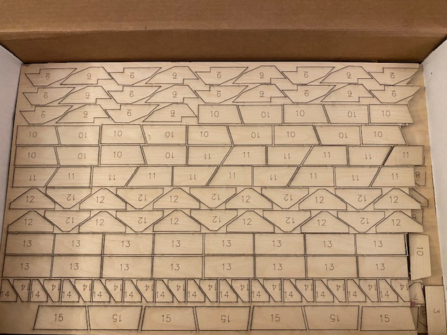
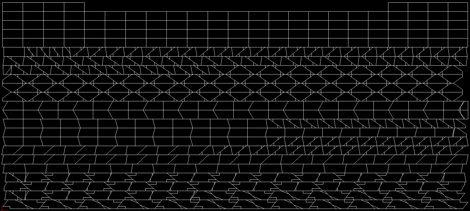
If you have a scanner large enough, that could work. I just measured all the parts on the drawings with a ruler with 1/64" increments (almost all of them lined up on a 1/16" increment anyway) and made drawings from those measurements in a 2D CAD program. I also combined a lot of edges with mine so that one pass from the laser cut multiple parts (I forgot to photograph this, but I attached a screenshot of the drawing I used with the laser cutter to show what I mean). This occasionally had the effect of the laser cutting a bit of material into the edge of one part when cutting another, but it's subtle and I've only seen a few minor instances of it so far.
For the nose ribs I used a method similar to what ITman496 suggests - I put my camera on a tripod and took a photo of the plans hanging on the wall, then another photo with a 0.5" grid held over the nose rib, and used GIMP to make the grid photo partially transparent and line up with the background photo. I then traced the outline of the nose rib in InkScape and saved it as a DXF file. The InkScape DXF extension was broken (this may have been fixed, but I can't find the source for it) so I had to hack away at it a bit to make it work. You may be able to use SVG with your laser cutter and skip this step (or just use a different drawing program).
One crucial thing to remember is the laser is very fine and very precise, but still has kerf. After making my drawings but before copying them into the pattern that was fed to the laser cutter, I offset all the lines .025" outward. This gave me slightly oversized parts (the parts list for the kit suggests these should be made from 7/8" [0.875"] wide strips of plywood, and a gusset I just measured is 0.914" tall) but I'd rather have that than slightly undersized.