timyandowAugust 24, 2024, 11:10pm
Anyone else question this part of the plans while building? I can't figure out why this is not adding up and what I am failing to see here...
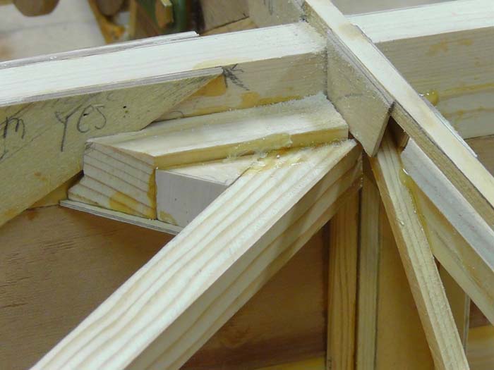
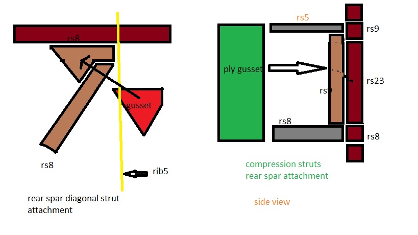
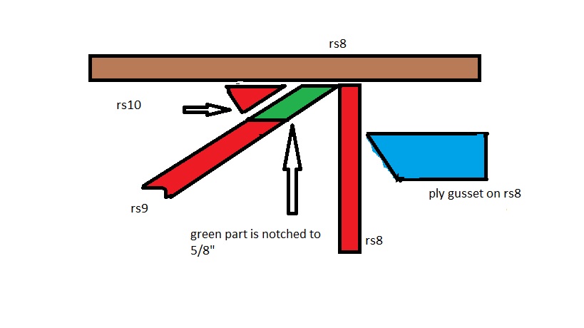
Area G calls for a 3 inch RS9 with a 45 degree angle and a Rs10 corner block which will have the RS8 diagonal against it at a 45 degree angle. The plans make this RS9 look like the same height as the RS8 doubler on the spar with everything equal in size. Should the 3 inch RS9 that I am pointing to actually be an RS8? Or should I just let this hang low? I am attaching a picture of what this really looks like alongside what the plans have this looking like.
I know this is a very small detail but I've learned small details can become big details downstream, so I am just trying to understand 100% why this is.
Thanks
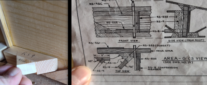